Precision Pinch Valve Pump for Safer Surgeries

Introduction

In surgical environments, precision in fluid management is critical. This patented pump system, equipped with a highly accurate pinch valve mechanism, addresses the unique needs of surgical fluid control. Designed for the complexity and high standards of surgical procedures, this pump offers precise, real-time fluid management, ensuring both patient safety and operational efficiency. Companies in the surgical equipment and medical devices industry can capitalize on this opportunity to deliver unparalleled fluid control solutions in surgery.

How It Works

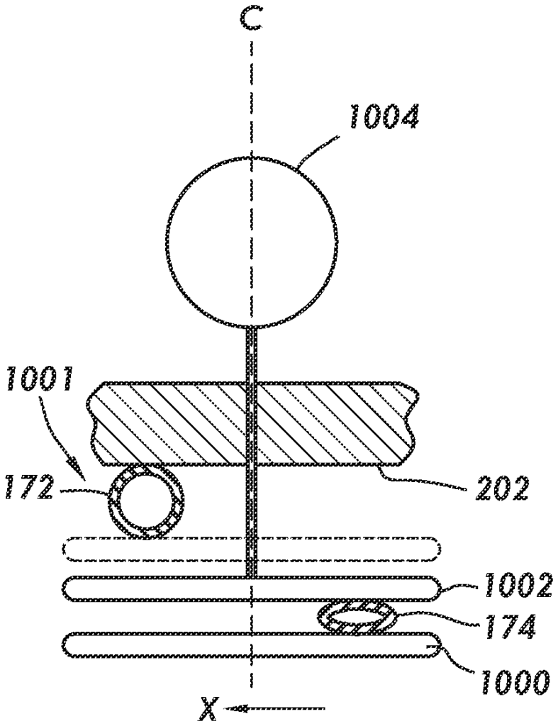
The pump system utilizes a pinch valve design to regulate fluid flow with remarkable precision. Unlike traditional pumps, this system can quickly adjust flow rates and minimize interruptions, which is essential in dynamic surgical environments. The pinch valve design also reduces the risk of backflow and contamination, creating a more secure environment for fluid handling. Furthermore, its control interface is intuitive, enabling easy adjustments to accommodate varying surgical needs and complexities.

Key Benefits

  • Enhanced Precision: The pinch valve design offers unmatched control over fluid flow, allowing surgeons and staff to adjust fluid rates accurately without disrupting the procedure.
  • Safety and Reliability: The system minimizes contamination risk by maintaining closed, sterile fluid pathways. This is especially valuable in infection-prone environments, providing peace of mind for surgical teams.
  • Real-Time Adjustments: Fluid requirements can change instantly during surgery. This pump allows for real-time flow adjustments, ensuring the surgical team can respond swiftly and with confidence.
  • Reduced Downtime and Maintenance: The pinch valve system has fewer moving parts than traditional pumps, leading to less wear and tear. This reduces maintenance needs and increases the device’s lifespan, providing a cost-effective solution for healthcare facilities.

Why License This Technology

This pump system with a pinch valve mechanism is a transformative solution for fluid management in surgeries. For medical device companies, licensing this technology means gaining access to a high-value, reliable product that meets the stringent needs of modern surgical settings. Incorporating this system into product offerings enhances brand value and provides surgeons with a new tool for fluid control that increases accuracy, efficiency, and safety in the operating room. Embrace the opportunity to be at the forefront of surgical innovation with this cutting-edge fluid management system.

Pump systems with pinch valves for surgical procedures. At least some of the example embodiments are pump systems including a stationary housing defining a front face. A tube support extends outwardly from the front face for aligning and supporting a first tube and a second tube. At least one pinch member is movable relative to the tube support by a power actuator operably coupled to the at least one pinch member and configured to have three orientations that define: a first arrangement of the pinch member relative to the tube support configured to pinch closed the first tube, a second arrangement of the at least one pinch member relative to the tube support configured to pinch closed the second tube, and a third arrangement of the at least one pinch member relative to the tube support configured to pinch closed neither the first tube nor the second tube.

What is claimed is:

1. A pump system including an outflow pump, the pump system comprising:

a stationary housing defining an internal volume and a front face outside the internal volume extending in a first direction and a second direction transverse to the first direction;
the stationary housing including at least one tube support outside the internal volume extending outwardly from the front face for aligning and supporting a first tube and a second tube;
at least one pinch member being movable relative to the at least one tube support;

a power actuator disposed in the internal volume and operably coupled to the at least one pinch member, the power actuator configured to have three orientations that define:

a first arrangement of the at least one pinch member relative to the at least one tube support configured to pinch closed the first tube,
a second arrangement of the at least one pinch member relative to the at least one tube support configured to pinch closed the second tube, and
a third arrangement of the at least one pinch member relative to the at least one tube support configured to pinch closed neither the first tube nor the second tube;
the at least one tube support including a t-shaped bracket having a central post extending outwardly from the front face along a longitudinal central axis and including a support beam attached to and extending across the central post and spaced from and along the front face in the second direction;
the t-shaped bracket defining a bracket cavity leading to the internal volume and extending through the central post and into the support beam;
the t-shaped bracket defining a first tube notch configured to accept the first tube and a second tube notch configured to accept the second tube;

the power actuator including:

a sliding shaft extending along the longitudinal central axis through the front face and out of the internal volume into the bracket cavity;

a solenoid assembly coupled to the sliding shaft, the sliding shaft movable by the solenoid assembly along the longitudinal central axis to:

a first translational position to move the at least one pinch member to the first arrangement,
a second translational position to move the at least one pinch member to the second arrangement, and
a third translational position to move the at least one pinch member to the third arrangement;
a first pinch bar extending radially from the longitudinal central axis at a distal end of the sliding shaft in a first lateral direction along the support beam into the bracket cavity adjacent the first tube notch and configured to move toward the front face when the sliding shaft is moved to the first translational position while maintaining spacing of a first notch width with the front face when the sliding shaft moves to the third translational position; and
a second pinch bar extending radially from the longitudinal central axis in a second lateral direction opposite the first lateral direction into the bracket cavity and offset from the first pinch bar along the longitudinal central axis by a second notch width and along and spaced from the support beam and configured to move away the front face when the sliding shaft is moved to the second translational position while maintaining spacing of the second notch width with the front face when the sliding shaft moves to the third translational position.

2. The pump system as set forth in claim 1, wherein the solenoid assembly includes:

a first solenoid having a first coil fixedly attached to the stationary housing and having a first solenoid core extending and movable along a first core axis in parallel to the longitudinal central axis, the first solenoid configured to move the first solenoid core in a first core direction along the first core axis from a first core initial position corresponding to the third translational position of the sliding shaft to a first core extended position corresponding to the first translational position of the sliding shaft in response to the first coil being energized and return to the first core initial position in response to the first coil not being energized;
a second solenoid having a second coil fixedly attached to the stationary housing and having a second solenoid core extending and movable along a second core axis in parallel to the longitudinal central axis and spaced from the first core axis, the second solenoid configured to move the second solenoid core in a second core direction along the second core axis opposite the first core direction from a second core initial position corresponding to the third translational position of the sliding shaft to a second core extended position corresponding to the second translational position of the sliding shaft in response to the second coil being energized and return to the second core initial position in response to the second coil not being energized; and
a z-shaped bracket including a central portion extending rectilinearly in parallel to the longitudinal central axis and including a first arm extending orthogonally to the longitudinal central axis and attached to the first solenoid core and the sliding shaft and a second arm extending orthogonally to the longitudinal central axis and attached to the second solenoid core for moving the sliding shaft along the longitudinal central axis.
3. The pump system as set forth in claim 1, further including a solenoid controller coupled to the solenoid assembly and configured to reduce a voltage supplied to the solenoid assembly from an initial voltage to a predetermined reduced voltage after a predetermined amount of time thereby reducing an amount of power required to maintain a pinch applied by the at least one pinch member in the first translational position of the sliding shaft and by the at least one pinch member in the second translational position of the sliding shaft in the second translational position of the sliding shaft.

4. A pump system including an outflow pump, the pump system comprising:

a stationary housing defining an internal volume and a front face outside the internal volume extending in a first direction and a second direction transverse to the first direction;
the stationary housing including at least one tube support outside the internal volume extending outwardly from the front face for aligning and supporting a first tube and a second tube;
at least one pinch member being movable relative to the at least one tube support;

a power actuator disposed in the internal volume and operably coupled to the at least one pinch member, the power actuator configured to have three orientations that define:

a first arrangement of the at least one pinch member relative to the at least one tube support configured to pinch closed the first tube,
a second arrangement of the at least one pinch member relative to the at least one tube support configured to pinch closed the second tube, and
a third arrangement of the at least one pinch member relative to the at least one tube support configured to pinch closed neither the first tube nor the second tube;
the at least one tube support including a t-shaped bracket having a central post extending outwardly from the front face along a longitudinal central axis and including a support beam attached to and extending across the central post and spaced from and along the front face in the second direction;
the t-shaped bracket defining a bracket cavity leading to the internal volume and extending through the central post and into the support beam;
the t-shaped bracket defining a first tube notch configured to accept the first tube and a second tube notch configured to accept the second tube;

the power actuator including:

a sliding shaft extending along the longitudinal central axis through the front face and out of the internal volume into the bracket cavity; and

a solenoid assembly coupled to the sliding shaft, the sliding shaft movable by the solenoid assembly along the longitudinal central axis to:

a first translational position to move the at least one pinch member to the first arrangement,
a second translational position to move the at least one pinch member to the second arrangement, and
a third translational position to move the at least one pinch member to the third arrangement;
a first solenoid having a first coil fixedly attached to the stationary housing and having a first solenoid core extending and movable along a first core axis in parallel to the longitudinal central axis, the first solenoid configured to move the first solenoid core in a first core direction along the first core axis from a first core initial position corresponding to the third translational position of the sliding shaft to a first core extended position corresponding to the first translational position of the sliding shaft in response to the first coil being energized and return to the first core initial position in response to the first coil not being energized;
a second solenoid having a second coil fixedly attached to the stationary housing and having a second solenoid core extending and movable along a second core axis in parallel to the longitudinal central axis and spaced from the first core axis, the second solenoid configured to move the second solenoid core in a second core direction along the second core axis opposite the first core direction from a second core initial position corresponding to the third translational position of the sliding shaft to a second core extended position corresponding to the second translational position of the sliding shaft in response to the second coil being energized and return to the second core initial position in response to the second coil not being energized; and
a z-shaped bracket including a central portion extending rectilinearly in parallel to the longitudinal central axis and including a first arm extending orthogonally to the longitudinal central axis and attached to the first solenoid core and the sliding shaft and a second arm extending orthogonally to the longitudinal central axis and attached to the second solenoid core for moving the sliding shaft along the longitudinal central axis.
5. The pump system as set forth in claim 4, further including a solenoid controller coupled to the solenoid assembly and configured to reduce a voltage supplied to the solenoid assembly from an initial voltage to a predetermined reduced voltage after a predetermined amount of time thereby reducing an amount of power required to maintain a pinch applied by the at least one pinch member in the first translational position of the sliding shaft and by the at least one pinch member in the second translational position of the sliding shaft in the second translational position of the sliding shaft.

Share

Title

Pump system with pinch valve for fluid management in surgical procedures and method of operation thereof

Inventor(s)

Mathew Mitchell, Mikhael LYSSOUNKINE, William Sant

Assignee(s)

Smith and Nephew Orthopaedics AG, Smith and Nephew Asia Pacific Pte Ltd, Smith and Nephew Inc

Patent #

11408416

Patent Date

August 9, 2022

Inquire about this intellectual property

Learn more about "Precision Pinch Valve Pump for Safer Surgeries"