Additive Manufacturing of a Wireless Ceramic High Temperature and Pressure Sensor

Introduction

Maintaining situational awareness of the weapon environment is desirable for developing the next generation of robust missile and munition (M&M) systems that can withstand the extreme acceleration, temperature, and pressure conditions that are presented by traditional fighter and hypersonic aircraft. In addition, tracking the temperature and pressure of high temperature turbines used in turbojets both for aircraft and energy production is highly desirable. Conventional techniques for remotely monitoring munition assets are primarily performed by proximate environmental monitoring by fuel sensors, accelerometers, surface acoustic wave sensors, chemical resistors, and temperature sensors. These are limited to storage and transportation purposes and typically have a limited temperature range, e.g., -55 °C to 125 °C.

Conventional temperature sensors used in the evaluation of M&M systems and turbine systems include thermocouples, thermistors, resistance thermometers, quartz thermometers, which all include a metallic coil inductor. Due to the oxidation of the metallic coil inductor, these temperature sensors cannot be used in high temperature environments for prolonged periods of time and can only be used under wired measurement conditions.

Conventional pressure sensors used in these applications include passive pressure sensors based on resistive or capacitive sensing mechanisms. These sensors also require a wire interconnection and they cannot operate effectively in high temperature environments. Moreover, pressure sensors that utilize a patch antenna operate within a limited temperature range, e.g., -55 °C to 125 °C, because of the metallic wire used with the patch antenna.

The technology developed at FSU comprises a wireless temperature and pressure sensor which includes a ceramic coil inductor having ceramic material and a relatively high volume fraction of carbon nanotubes. The combination leverages the remarkable electrical and mechanical properties (stiff and strong) of carbon nanotubes (CNTs) and the thermal properties (temperature sensitivity) of ceramic materials.

Generally, the temperature sensors comprise a ceramic coil inductor that is formed of a ceramic composite and a thin film polymer-derived ceramic (PDC) nanocomposite having a dielectric constant that increases monotonically with temperature and the pressure sensors comprise a ceramic coil inductor formed of a ceramic composite, which includes carbon nanotubes and/or carbon nanofibers. This novel technology has the potential to revolutionize the space industry, defense industry, and engineering.

Advantages

The ability to provide real-time, in-flight monitoring of systems that operate in high temperature and pressure environments

The ability to maintain safety and effectiveness of critical parts and materials without the need for extensive nondestructive evaluation (NDE) (for temperature sensors), thereby reducing cost and time

On-demand tracking and assessing of the status of systems over extended periods, based upon changing conditions
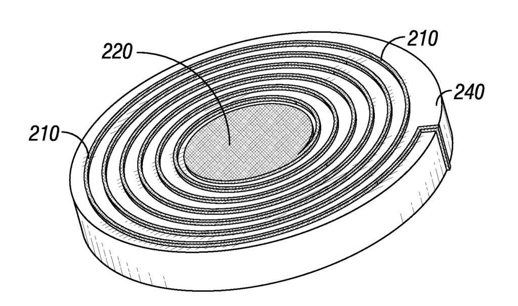
Temperature sensors, pressure sensors, methods of making the same, and methods of detecting pressures and temperatures using the same are provided. In an embodiment, the temperature sensor includes a ceramic coil inductor having a first end plate and a second end plate, wherein the ceramic coil inductor is formed of a ceramic composite that comprises carbon nanotubes or, carbon nanofibers, or a combination of carbon nanotubes and carbon nanofibers thereof dispersed in a ceramic matrix; and a thin film polymer-derived ceramic (PDC) nanocomposite disposed between the first and the second end plates, wherein the thin film PDC nanocomposite has a dielectric constant that increases monotonically with temperature.

We claim:

1. A temperature sensor comprising:

a ceramic coil inductor having a first end plate and a second end plate, wherein the ceramic coil inductor is formed of a ceramic composite that comprises carbon nanotubes, carbon nanofibers, or a combination thereof dispersed in a ceramic matrix; and
a thin film polymer-derived ceramic (PDC) nanocomposite disposed between the first and the second end plates, wherein the thin film PDC nanocomposite has a dielectric constant that increases monotonically with temperature.
2. The temperature sensor of claim 1, wherein the ceramic coil inductor is configured to communicate with an external radio frequency antenna.
3. The temperature sensor of claim 1, further comprising a patch antenna configured to communicate with an external radio frequency antenna, wherein the patch antenna is attached to the first end plate of the ceramic coil inductor.
4. The temperature sensor of claim 1, wherein the volume fraction of carbon nanotubes in the ceramic composite is about 15% to about 70%.
5. The temperature sensor of claim 1, wherein the ceramic matrix comprises a PDC material.
6. The temperature sensor of claim 1, wherein the ceramic composite comprises single-walled carbon nanotubes, multi-walled carbon nanotubes, or a combination thereof.

7. A pressure sensor comprising:

a ceramic coil inductor having a first end plate and a second end plate, wherein the ceramic coil inductor is formed of a ceramic composite that comprises carbon nanotubes, carbon nanofibers, or a combination thereof dispersed in a ceramic matrix; and
a polymer-derived ceramic (PDC) nanocomposite structure disposed between the first and the second end plates, wherein the PDC nanocomposite structure has walls that define an internal cavity having a first cavity surface and an opposed second cavity surface,
wherein the first and second cavity surfaces are spaced a distance from one another.
8. The pressure sensor of claim 7, wherein the volume fraction of carbon nanotubes in the ceramic composite is about 15% to about 70%.
9. The pressure sensor of claim 7, wherein the ceramic matrix comprises a PDC material.
10. The pressure sensor of claim 7, wherein the ceramic composite comprises single-walled carbon nanotubes, multi-walled carbon nanotubes, or a combination thereof.

11. A method for making a wireless temperature or pressure sensor, the method comprising:

forming a ceramic coil inductor having a first end plate and a second end plate, wherein the ceramic coil inductor comprises carbon nanotubes, carbon nanofibers, or a combination thereof dispersed in a ceramic matrix; and
providing a polymer-derived ceramic (PDC) nanocomposite between the first end plate and the second end plate.
12. The method of claim 11, wherein the PDC nanocomposite is in the form of a thin film and has a dielectric constant that increases monotonically with temperature.
13. The method of claim 12, further comprising attaching a patch antenna to the first end plate of the ceramic coil inductor.
14. The method of claim 11, wherein the ceramic matrix comprises a PDC material.

15. The method of claim 11, wherein the sensor is the temperature sensor and the manufacturing process comprises:

providing a mixture of a liquid-state pre-ceramic polymer and carbon nanotubes, carbon nanofibers, or a combination of carbon nanotubes and carbon nanofibers;
disposing the mixture on a support;
exposing the mixture to ultraviolet light effective to substantially cure the liquid-state pre-ceramic polymer; and
pyrolyzing the mixture at a temperature and for a time effective to form the ceramic coil inductor or the PDC nanocomposite.

16. The method of claim 11, wherein the sensor is a temperature sensor and the manufacturing process comprises:

providing a mixture of a liquid-state pre-ceramic polymer and carbon nanotubes or carbon nanofibers, or a combination of carbon nanotubes and carbon nanofibers;
disposing a first portion of the mixture on a support;
exposing the first portion of the mixture to ultraviolet light effective to substantially cure the liquid-state pre-ceramic polymer of the first portion;
disposing a second portion of the mixture on the first portion;
exposing the second portion of the mixture to ultraviolet light effective to substantially cure the liquid-state pre-ceramic polymer of the second portion; and
pyrolyzing the first and second portions of the mixture at a temperature and for a time effective to form the ceramic coil inductor or the PDC nanocomposite.

17. The method of claim 11, wherein the sensor is the pressure sensor and the manufacturing process comprises:

providing a mixture of a liquid-state pre-ceramic polymer and carbon nanotubes, carbon nanofibers, or a combination of carbon nanotubes and carbon nanofibers;
disposing the mixture on a support;
exposing the mixture to ultraviolet light effective to substantially cure the liquid-state pre-ceramic polymer; and
pyrolyzing the mixture at a temperature and for a time effective to form the ceramic coil inductor.

18. The method of claim 11, wherein the sensor is a pressure sensor and the manufacturing process comprises:

providing a mixture of a liquid-state pre-ceramic polymer and carbon nanotubes, carbon nanofibers, or a combination of carbon nanotubes and carbon nanofibers;
disposing a first portion of the mixture on a support;
exposing the first portion of the mixture to ultraviolet light effective to substantially cure the liquid-state pre-ceramic polymer of the first portion;
disposing a second portion of the mixture on the first portion;
exposing the second portion of the mixture to ultraviolet light effective to substantially cure the liquid-state pre-ceramic polymer of the second portion; and
pyrolyzing the first and second portions of the mixture at a temperature and for a time effective to form the ceramic coil inductor.

19. The method of claim 11, wherein the sensor is the pressure sensor and the manufacturing process comprises:

providing a mixture of a liquid-state pre-ceramic polymer and carbon nanotubes, carbon nanofibers, or a combination of carbon nanotubes and carbon nanofibers;
disposing a first portion of the mixture on a first support;
exposing the first portion of the mixture to ultraviolet light effective to substantially cure the liquid-state pre-ceramic polymer of the first portion;
subjecting the first portion of the mixture to pyrolysis at a temperature and time effective to form a first section of the PDC nanocomposite, wherein the first portion comprises a first cavity surface;
metallizing the first portion of the PDC nanocomposite;
disposing a second portion of the mixture on a second support;
exposing the second portion of the mixture to ultraviolet light effective to substantially cure the liquid-state pre-ceramic polymer of the second portion;
pyrolyzing the second portion of the mixture at a temperature and for a time effective to form a second section of the polymer derived-ceramic nanocomposite, wherein the second portion comprises a second cavity surface;
metallizing the second portion of the PDC nanocomposite; and
joining the first portion with the second portion to form the PDC nanocomposite.
20. The method of claim 15, wherein the mixture further comprises a UV sensitizer.
21. The method of claim 15, wherein the liquid-state pre-ceramic polymer comprises polysilazane.

22. A method of detecting a change in temperature, the method comprising:

placing one or more temperature sensors of claim 1 in an environment; and
measuring a frequency shift of an electromagnetic signal induced in the ceramic coil to detect a change in temperature of the environment.
23. The method of claim 22, wherein the one or more temperature sensors are configured to detect the change in temperature in the environment with a temperature in the range from about 25° C. to about 1000° C.

24. A method of detecting a change in pressure, the method comprising:

placing one or more pressure sensors of claim 7 in an environment; and
measuring a frequency shift of an electromagnetic signal induced in the ceramic coil inductor to detect a change in pressure of the environment.
25. The method of claim 24, wherein a change in the distance between the first surface of the protrusion and the second cavity surface results in the frequency shift, and wherein the change in distance is function of pressure within the environment.
26. The method of claim 25, wherein the one or more pressure sensors are configured to detect the change in pressure in the environment with a pressure in the range from about 0 psi to about 40,000 psi.

Share

Title

Temperature and pressure sensors and methods

Inventor(s)

Chengying Xu, Amanda Schrand

Assignee(s)

Florida State University Research Foundation Inc, US Air Force

Patent #

20180195879

Patent Date

July 12, 2018

Inquire about this intellectual property

Learn more about "Additive Manufacturing of a Wireless Ceramic High Temperature and Pressure Sensor"