Innovative Ear Pressure Equalization System

Introduction

This tympanic membrane pressure equalization tube delivery system provides a safer and more efficient method for treating patients with chronic ear infections or Eustachian tube dysfunction. Designed to deliver pressure equalization tubes with precision, this system reduces the risks associated with traditional procedures and enhances the patient experience. For medical device companies and healthcare providers, this technology offers an advanced solution to a common problem in pediatric and adult ear care, ensuring better outcomes with minimal discomfort.

The Challenge: Treating Chronic Ear Infections Safely

Chronic ear infections and persistent Eustachian tube dysfunction are particularly prevalent among children, often requiring the placement of pressure equalization (PE) tubes to prevent fluid buildup and improve hearing. Traditional methods of inserting these tubes can be invasive, uncomfortable, and carry risks of complications. This has led to a growing demand for more precise and less traumatic delivery systems that ensure accurate placement of tubes while minimizing patient discomfort. Healthcare professionals need reliable devices that simplify the procedure and improve overall outcomes.

Precision Delivery for Effective Treatment

This innovative ear pressure equalization system addresses these challenges by offering a delivery method that enhances the precision and control of tube placement. The system is designed to streamline the insertion process, reducing the potential for complications, and making the procedure safer for patients, especially in pediatric cases. Its intuitive design allows healthcare professionals to perform the procedure more quickly and with greater accuracy, ensuring that the PE tubes are securely placed for optimal pressure equalization. The system’s improved delivery mechanism also helps reduce discomfort and recovery time for patients.

Key Benefits for Healthcare Providers and Patients

For healthcare providers, this technology offers a significant advantage by improving the efficiency and safety of PE tube placements. Otolaryngologists and audiologists can use this system to provide better care for patients with chronic ear infections, reducing the need for repeat procedures and minimizing the risk of complications. Pediatricians will benefit from the system’s ability to make the procedure less traumatic for children, while healthcare facilities can reduce the overall costs and time associated with ear surgeries. For patients, especially children, this system ensures a more comfortable, effective treatment with faster recovery.

Invest in Advanced Ear Care Solutions

Licensing this ear pressure equalization system positions your company at the forefront of medical device innovation in ear care. By offering a more effective and patient-friendly solution for PE tube placement, your business can meet the growing demand for safer, more efficient ear treatments. This technology provides an opportunity to improve patient outcomes, simplify procedures, and enhance the quality of care in both pediatric and adult ear health. It’s a valuable investment for companies looking to deliver cutting-edge solutions in the field of otolaryngology.
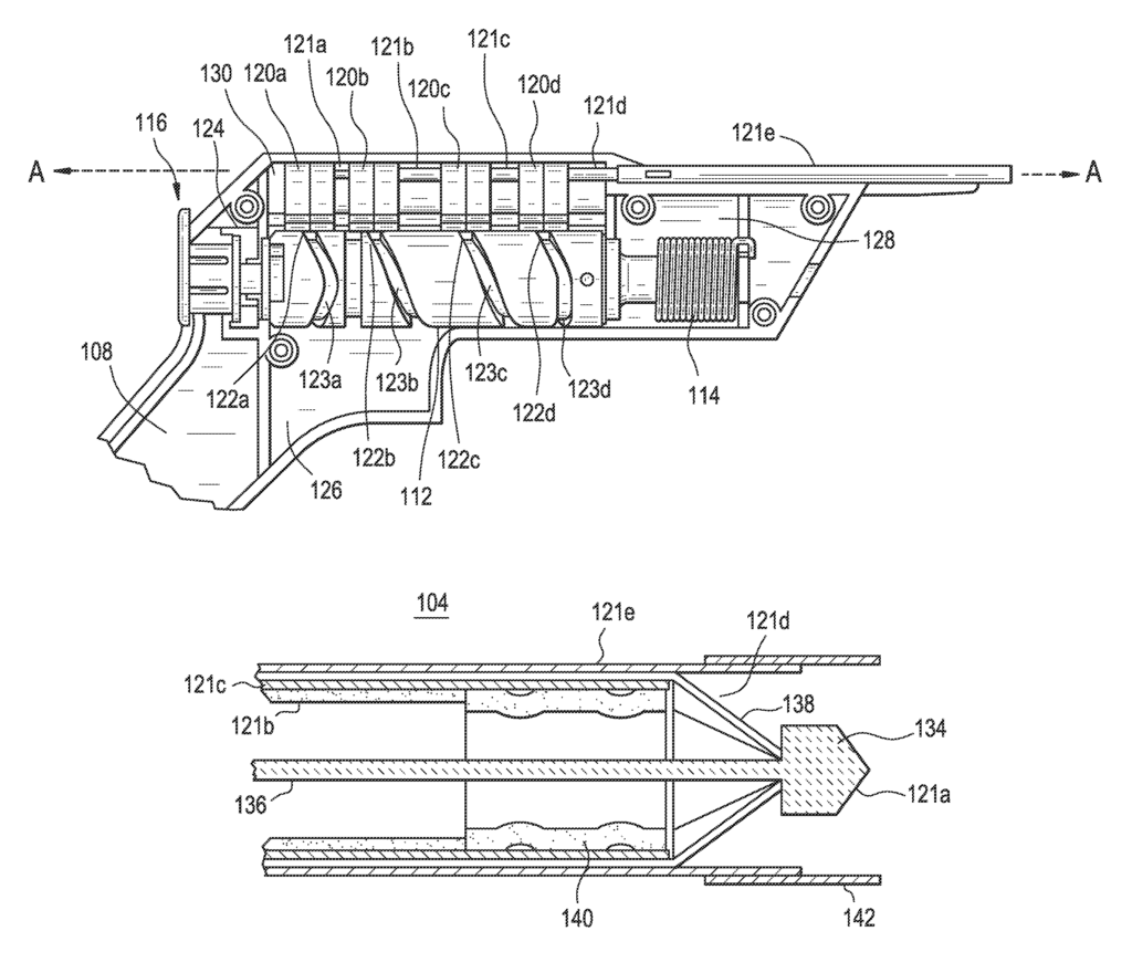
Systems and methods are provided for automatically forming an incision in a tympanic membrane of an ear and placing a tympanic membrane pressure equalization tube into the incision. The systems include a housing with a shaft extending therefrom. A mechanism is disposed within the housing. A distal end of the shaft is placed against a tympanic membrane, and the mechanism is triggered to causes the tympanic membrane to be automatically incised and dilated and a tympanic membrane pressure equalization tube to be placed in the dilated incision.

What is claimed is:

1. A system for forming an incision in a tympanic membrane and delivering a pressure equalization tube into the incision, the system comprising:

(a) a housing including a handle;

(b) an elongate shaft assembly coupled with the housing, the shaft assembly comprising:

(i) an outer shaft having a blunt distal tip portion,
(ii) a cutter linearly moveable within the outer shaft,
(iii) a pusher slidably disposed over the cutter within the outer shaft,
(iv) a pressure equalization tube slidably disposed about the cutter at a distal end of the pusher,
(v) a shield slidably disposed over the pusher and the pressure equalization tube, and (vi) a dilator slidably disposed over the shield, wherein the dilator has an expandable portion, wherein the shield is interposed between the dilator and the pressure equalization tube such that the shield separates the dilator from the pressure equalization tube along a radial dimension;

(c) a cam assembly comprising:

(i) a cam shaft rotationally coupled within the housing, the cam shaft including a first cam profile, a second cam profile, a third cam profile, and a fourth cam profile;
(ii) a first cam follower moveably coupled to the first cam profile, the first cam follower attached to the cutter;
(iii) a second cam follower moveably coupled to the second cam profile, the second cam follower attached to the pusher;
(iv) a third cam follower moveably coupled to the third cam profile, the third cam follower attached to the shield;
(v) a fourth cam follower moveably coupled to the fourth cam profile, the fourth cam follower attached to the dilator;
(d) a spring biased between the housing and the cam shaft, the spring having a wound position which places a torsional load on the cam shaft, and a released position; and
(e) a release member moveably coupled to the cam shaft, the release member having a first position which maintains the spring in the wound position and a second position which allows the spring to move into the released position;
wherein the cam profiles are arranged and configured such that, when the release member is moved into the released position, the spring is released to move the cam shaft and cause the cam followers to linearly move respective portions of the shaft assembly to form an incision in a tympanic membrane using the cutting member, dilate the incision using the dilator, and advance the pressure equalization tube out of the shield and into the incision using the pusher.
2. The system of claim 1, wherein the housing comprises a first housing portion and a second housing portion, and wherein each housing portion is a molded clamshell.
3. The system of claim 2, wherein the housing portions form a cam shaft chamber, a cam follower chamber, a spring chamber, and a trigger mechanism chamber.
4. The system of claim 1, wherein the outer shaft is constructed from rigid tubing.
5. The system of claim 1, wherein the outer shaft comprises an outer wall, an inner wall, and a space therebetween.
6. The system of claim 5, wherein a negative air pressure source is connected to the space between the outer wall and the inner wall.
7. The system of claim 1, wherein the cutting member comprises an elongate wire with a diamond headed tip.
8. The system of claim 1, wherein the shield comprises an elongate tube.
9. The system of claim 1, wherein the pressure equalization tube comprises a grommet with a lumen, a medial flange, and a lateral flange.
10. The system of claim 9, wherein the medial and lateral flanges are compressed within the shield.
11. The system of claim 10, wherein the pressure equalization tube includes internal wire scaffolding.
12. The system of claim 10, wherein the pressure equalization tube is constructed from an elastomeric material and includes flexible portions between the lumen and flanges.
13. The system of claim 10, wherein the flanges include notches that facilitate compression of the tube within the shield.
14. The system of claim 1, wherein the pusher comprises an elongate tube.
15. The system of claim 1, wherein the dilator comprises an elongate tube with a distal tip, the distal tip being capable of expanding from a narrow position to an open position.
16. The system of claim 15, wherein the distal tip comprises a plurality of members which are spring biased in the narrow position and can be forcibly opened into the open position.
17. The system of claim 1, wherein the cam shaft comprises an elongate cylinder, with first and second ends rotationally attached to the housing, a mid-section therebetween, and a spring holder extending from the second end.
18. The system of claim 15, wherein the cam profiles each comprise a patterned groove in the mid-section.
19. The system of claim 1, wherein the cam followers each comprise a block which is slidably housed in the housing, each block including a drive pin for following a respective cam profile.
20. The system of claim 19, wherein the blocks are arranged linearly with respect to the elongate shaft.
21. The system of claim 1, wherein a link couples the release member to the cam shaft, and wherein the release member pushes the link to release the cam shaft when moved into the second position.
22. The system of claim 1, wherein a link couples the release member to the cam shaft, and wherein the release member, when moved laterally, releases the link to release the cam shaft when moved into the second position.
23. The system of claim 1, wherein the release member is selected from the group comprising a button, a trigger or a switch.

24. A system for forming an incision in a tympanic membrane and delivering a pressure equalization tube into the incision, the system comprising:

(a) a housing including a handle;

(b) an elongate shaft assembly coupled with the housing, the shaft assembly comprising:

(i) an outer shaft having a blunt distal tip portion,
(ii) a cutter linearly moveable within the outer shaft,
(iii) a pusher slidably disposed over the cutter within the outer shaft,
(iv) a pressure equalization tube slidably disposed about the cutter at a distal end of the pusher,
(v) a shield slidably disposed over the pusher and the pressure equalization tube and slidably movable relative to the outer shaft, and
(vi) a dilator slidably disposed over the shield, wherein the dilator has an expandable portion, wherein the pressure equalization tube is longitudinally interposed between the distal end of the pusher and the expanding portion of the dilator.
25. The system of claim 24, wherein the outer shaft is constructed from rigid tubing.
26. The system of claim 24, wherein the cutting member comprises an elongate wire with a diamond headed tip.
27. The system of claim 24, wherein the shield comprises an elongate tube.
28. The system of claim 24, wherein the pressure equalization tube comprises a grommet with a lumen, a medial flange, and a lateral flange.
29. The system of claim 28, wherein the medial and lateral flanges are compressed within the shield.
30. The system of claim 29, wherein the pressure equalization tube includes internal wire scaffolding.
31. The system of claim 29, wherein the pressure equalization tube is constructed from an elastomeric material and includes flexible portions between the lumen and flanges.
32. The system of claim 29, wherein the flanges include notches that facilitate compression of the tube within the shield.
33. The system of claim 24, wherein the pusher comprises an elongate tube.
34. The system of claim 24, wherein the dilator comprises an elongate tube with a distal tip, the distal tip being capable of expanding from a narrow position to an open position.
35. The system of claim 34, wherein the distal tip comprises a plurality of members which are spring biased in the narrow position and can be forcibly opened into the open position.

Share

Title

Tympanic membrane pressure equalization tube delivery system

Inventor(s)

Greg Liu, Rohit Girotra, John H. Morriss, Julie D. Vrany, Hung V. Ha, Bryan Knodel, Jeffrey A. Walker, Thomas Daniel Gross, Mathew D. Clopp, Bernard H. Andreas

Assignee(s)

Tusker Medical Inc

Patent #

8864774

Patent Date

October 21, 2014

Inquire about this intellectual property

Learn more about "Innovative Ear Pressure Equalization System"