Optimizing Light Transmission for Critical Applications

Introduction

Whether in surgical settings, telecommunications, or industrial applications, the need for highly efficient, precise, and reliable light transmission systems is constantly growing. Connecting light cables to illuminators, particularly in systems where precision and intensity matter, requires technology that ensures seamless and efficient light transfer. Our patented system is designed to optimize the connection between light cables and illuminators, offering superior performance for applications where lighting is critical.

The Gap in Current Lighting Systems

Current methods of connecting light cables to illuminators are often cumbersome and lack precision, leading to diminished light intensity, potential disconnects, and suboptimal performance. In critical environments—such as medical surgeries or optical communications—this inefficiency can have far-reaching consequences. Loss of light intensity or improper connections can disrupt procedures, delay operations, or cause costly malfunctions.

For industries relying on high-performance lighting solutions, such as healthcare, telecommunications, and manufacturing, ensuring maximum light transfer efficiency is paramount. However, current systems often fall short, leaving gaps that compromise both performance and safety.

An Innovative Connection System

This patented system offers a comprehensive solution to address the inefficiencies and risks associated with traditional lighting connection methods. Our innovative design ensures a seamless connection between the light cable and illuminator, maximizing light transmission and minimizing loss. The system also allows for easy and secure connections, ensuring that the light cable remains firmly in place during operation, reducing the risk of disruption in critical environments.

The device is engineered for high-performance environments, from medical settings requiring intense, focused light to industrial applications where precision illumination is necessary. The versatility of this system makes it adaptable for various uses, including automotive, aerospace, and optical communication industries, where precision lighting plays an essential role.

Superior Benefits

  1. Maximized Light Transmission: The advanced design ensures maximum light transfer with minimal loss, enhancing performance in high-intensity, precision lighting environments.
  2. Secure and Reliable Connections: With an intuitive connection mechanism, this system ensures that light cables remain securely connected, reducing the risk of interruptions during critical procedures or operations.
  3. Versatility Across Industries: Whether for medical, optical, or industrial applications, this system is adaptable to a wide range of industries requiring efficient lighting solutions.
  4. Improved Workflow and Efficiency: By minimizing light loss and ensuring secure connections, this system improves overall workflow, reducing downtime and ensuring smoother operations.

The Right Solution for Modern Lighting Needs

Licensing this cutting-edge system offers your organization the opportunity to improve light transmission efficiency, optimize workflows, and provide better service in critical lighting applications. This technology can enhance performance across various industries, ensuring precision and reliability when it matters most.
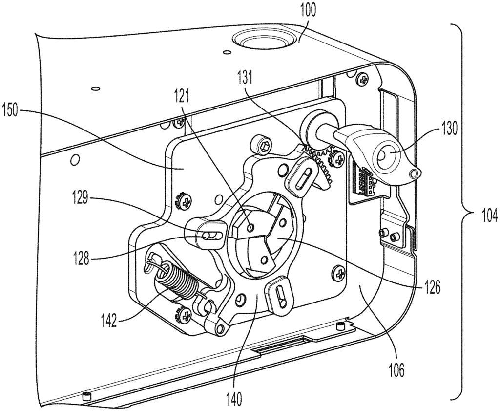
An illuminator including a receptacle for connecting a light cable to an illuminator. The receptacle includes a clamp assembly having a plurality of clamping jaws that are moveable from an open configuration in which a connecter of the light cable can be positioned between the clamping jaws for receiving light traveling in a light pathway in the illuminator to a closed configuration in which the clamping jaws completely block the light pathway, and a clutch that is movable between an engaged position for holding the clamping jaws in the open configuration and a disengaged position for allowing the clamping jaws to move to a gripped configuration and to the closed configuration, the clutch can be pushed by the connector when the connector is positioned between the clamping jaws to move the clutch out of the engaged position so that the clamp assembly moves the clamping jaws to the gripped configuration.

The invention claimed is:

1. An illuminator comprising a receptacle for connecting a light cable to an illuminator, the receptacle comprising:

a clamp assembly comprising a plurality of clamping jaws that are moveable by the clamp assembly from an open configuration in which a connecter of the light cable can be positioned between the clamping jaws for receiving light traveling in a light pathway in the illuminator to a closed configuration in which the clamping jaws completely block the light pathway; and
a clutch that is movable between an engaged position in which the clutch engages the clamp assembly for holding the clamping jaws in the open configuration and a disengaged position in which the clutch is disengaged from the clamp assembly for allowing the clamping jaws to move to a gripped configuration in which the clamping jaws grip onto the connector positioned between the clamping jaws and to the closed configuration, the clutch comprising a central portion that can be pushed by the connector when the connector is positioned between the clamping jaws to move the clutch out of the engaged position so that the clamp assembly moves the clamping jaws to the gripped configuration.
2. The illuminator of claim 1, wherein the clamp assembly comprises a locking guide operatively connected to each clamping jaw of the plurality of clamping jaws, the locking guide configured for moving between a first position for holding the clamping jaws in the open configuration and a second position for holding the jaws in the closed configuration.
3. The illuminator of claim 1, wherein the receptacle comprises a user-operated actuator operatively connected to the clamp assembly for moving the clamping jaws from the closed configuration to the open configuration.
4. The illuminator of claim 1, wherein each clamping jaw of the plurality of clamping jaws comprises a recessed portion adjacent to an overlapping portion so that in the closed configuration, the overlapping portion of each clamping jaw extends over the recessed portion of at least another clamping jaw of the plurality of clamping jaws.
5. The illuminator of claim 1 comprising a base plate comprising a first side and a second side opposite to the first side, wherein a plurality of protrusions of the clutch extend from the second side of the base plate to the first side of the base plate when the clutch is in the engaged position.
6. The illuminator of claim 1, wherein the plurality of clamping jaws comprises a plurality of inwardly facing gripping surfaces that are outwardly spaced from the central portion of the clutch when the clutch is in the engaged position.
7. The illuminator of claim 1, wherein the central portion of the clutch extends between the plurality of clamping jaws when the clutch is in the engaged position.
8. The illuminator of claim 1, wherein the clutch is configured to move translationally between the engaged position and the disengaged position in a direction orthogonal to a movement of the plurality of clamping jaws between the open configuration and the closed configuration.
9. The illuminator of claim 1 comprising a base plate, wherein the clamp assembly is positioned on a first side of the base plate and the clutch is positioned on a second side of the base plate that is opposite the first side of the base plate.
10. The illuminator of claim 9, wherein the clutch comprises a plurality of protrusions that extend between the second side of the base plate and the first side of the base plate for holding the locking guide in the first position.
11. The illuminator of claim 1 comprising a base plate for supporting the receptacle, wherein the central portion of the clutch fits into an aperture in the base plate.
12. The illuminator of claim 1, wherein the receptacle is configured to receive connectors having a range of diameters.
13. The illuminator of claim 1, wherein the connector of the light cable is for an endoscope.
14. The illuminator of claim 1, wherein the illuminator is configured to provide illuminating light to an endoscope via the light cable.
15. The illuminator of claim 1, wherein the illuminator comprises the light cable.
16. The illuminator of claim 1 comprising a lens for focusing light travelling in the light pathway to the central portion of the clutch.
17. The illuminator of claim 1 comprising a light pipe located in the central portion of the clutch.
18. The illuminator of claim 1, wherein the central portion of the clutch extends between an aperture of a base plate when the clutch is in the engaged position and in the disengaged position.
19. The illuminator of claim 1 comprising one or more guide posts that support the clutch between a back plate and a base plate.
20. The illuminator of claim 19, wherein the clutch comprises rolling pins configured to interface the one or more guide posts for reducing friction during clutch movement between the engaged position and the disengaged position with the clamp assembly.
21. The illuminator of claim 19, wherein the one or more guide posts comprise a hard stop that limits clutch movement between the engaged position and the disengaged position with the clamp assembly.

22. An illuminator comprising a receptacle for connecting a light cable to an illuminator, the receptacle comprising:

a plurality of clamping jaws; and
a locking guide operatively connected to each clamping jaw of the plurality of clamping jaws and configured for rotating about a light pathway between a first rotational position for holding the clamping jaws in an open configuration in which a connecter of the light cable can be positioned between the clamping jaws for receiving light traveling in the light pathway in the illuminator and a second rotational position for holding the clamping jaws in a closed configuration in which the clamping jaws completely block the light pathway; and
wherein each clamping jaw of the plurality of clamping jaws comprises at least one protrusion that slideably engages a respective slot in the locking guide for operatively connecting each clamping jaw of the plurality of clamping jaws to the locking guide.
23. The illuminator of claim 22, wherein the clamping jaws are moveable to a gripped configuration in which the clamping jaws grip onto the connector positioned between the clamping jaws.
24. The illuminator of claim 22, wherein each clamping jaw of the plurality of clamping jaws comprises a recessed portion adjacent to an overlapping portion so that in the closed configuration, the overlapping portion of each clamping jaw extends over the recessed portion of at least another clamping jaw of the plurality of clamping jaws.
25. The illuminator of claim 22, wherein the receptacle comprises a user-operated actuator operatively connected to the locking guide for moving the locking guide from the second position to the first position.
26. The illuminator of claim 22, wherein the locking guide is configured to automatically move the clamping jaws to the closed configuration when the gripped connector is removed from between the clamping jaws.
27. The illuminator of claim 22, wherein the locking guide is moveable to a third position for holding the clamping jaws in a gripped configuration in which the clamping jaws grip onto the connector positioned between the clamping jaws.
28. The illuminator of claim 22 comprising a clutch that is movable between an engaged position in which the clutch holds the locking guide in the first position and a disengaged position in which the clutch is disengaged from the locking guide for allowing the locking guide to move to the second position and to a third position, wherein the locking guide in the third position holds the clamping jaws in a gripped configuration in which the clamping jaws grip onto the connector positioned between the clamping jaws.
29. The illuminator of claim 28, wherein the locking guide comprises rolling pins configured to interface the clutch for reducing friction during clutch movement between the engaged position and the disengaged position with the locking guide.
30. The illuminator of claim 22, wherein the locking guide is spring loaded via a spring that attaches the locking guide to a base plate via machined hooks in the base plate.
31. The illuminator of claim 22, wherein the locking guide is spring loaded via a spring that attaches the locking guide to a base plate via machined apertures in the base plate.
32. The illuminator of claim 22, wherein the locking guide is spring loaded via a spring that attaches the locking guide to a base plate via machined hooks in the locking guide.
33. The illuminator of claim 22, wherein the locking guide is spring loaded via a spring that attaches the locking guide to a base plate via machined apertures in the locking guide.

34. An illuminator comprising a receptacle for connecting a light cable to an illuminator, the receptacle comprising:

a plurality of clamping jaws that are moveable from an open configuration in which a connecter of the light cable can be positioned between the jaws for receiving light traveling in a light pathway in the illuminator to a closed configuration in which the clamping jaws completely block the light pathway;
a locking guide operatively connected to the plurality of clamping jaws for moving the plurality of clamping jaws between the open configuration and the closed configuration, the locking guide being moveable between a first position configured for holding the clamping jaws in the open configuration, a second position configured for holding the clamping jaws in the closed configuration, and a third position configured for holding the clamping jaws in a gripped configuration in which the clamping jaws grip onto the connector positioned between the clamping jaws; and
a clutch that is movable between an engaged position for holding the locking guide in the first position and a disengaged position for allowing the locking guide to move to the second position and to the third position, the clutch comprising a central portion that can be pushed by the connector when the connector is positioned between the jaws to move the clutch out of the engaged position so that the locking guide moves the clamping jaws to the gripped configuration,
wherein the locking guide is configured to automatically move the clamping jaws to the closed configuration when the gripped connector is removed from between the clamping jaws.

35. A method for connecting a receptacle of an illuminator to a light cable, the method comprising:

using a locking guide in a first position to hold a plurality of clamping jaws in an open configuration, wherein the locking guide is operatively connected to each clamping jaw of the plurality of clamping jaws;
holding the locking guide in the first position via a clutch engaged with the locking guide;
positioning a connector of the light cable between the clamping jaws in the open configuration;
pushing the connector positioned between the jaws against a central portion of the clutch to disengage the clutch from the locking guide;
gripping the inserted connector positioned between the clamping jaws; and
automatically moving the clamping jaws to the closed configuration in response to removing the gripped connector from between the clamping jaws.
36. The method of claim 35, wherein gripping the inserted connector positioned between the clamping jaws comprises moving the clamping jaws to a gripped configuration.
37. The method of claim 35, wherein automatically moving the clamping jaws comprises automatically moving the locking guide to a second position that holds the clamping jaws in the closed configuration.
38. The method of claim 35, wherein automatically moving the clamping jaws comprises maintaining the clutch in the disengaged position.
39. The method of claim 35, wherein gripping the inserted connector comprises moving the locking guide from the first position in which the locking guide holds the clamping jaws in the open configuration to a second position in which the locking guide holds the clamping jaws in the gripped configuration.

Share

Title

Systems and methods for connecting a light cable to an illuminator

Inventor(s)

Wenjie Deng, Michelle SUN, Maziyar Keshtgar

Assignee(s)

Stryker Corp

Patent #

11698522

Patent Date

July 11, 2023

Inquire about this intellectual property

Learn more about "Optimizing Light Transmission for Critical Applications"