Precision Detection with Magnetic Field Technology

Introduction

This innovative detection system, utilizing a finely tuned magnetic field gradient, provides unparalleled accuracy in identifying materials. Designed for industries where matter detection is critical, this technology brings a fresh approach to detecting substances in complex environments, ensuring precise analysis even in challenging conditions. Its adaptable, reliable design makes it invaluable for applications ranging from medical imaging to industrial quality control, allowing organizations to expand their detection capabilities with confidence.

The Challenge: Detecting Matter in Diverse Conditions

Traditional detection systems often lack the adaptability needed to distinguish various materials in fluctuating conditions or complex environments. Whether in medical imaging or security screening, the inability to reliably detect specific substances poses risks to safety, quality, and efficiency. Standard detection methods may also fail to isolate materials accurately, resulting in inconsistencies that impact the performance and dependability of the analysis. With the growing need for precise detection across sectors, industries require an advanced solution that ensures reliable, real-time material identification.

Advanced Detection with Magnetic Field Precision

This system’s advanced method employs a magnetic field gradient, creating an environment where matter can be detected and analyzed with unparalleled accuracy. By manipulating magnetic fields to focus on specific matter signatures, the technology distinguishes between materials with high sensitivity, identifying subtle differences that conventional methods may overlook. This high-precision approach enables detection in real-time, minimizing errors and enhancing reliability. The adaptive design is suitable for diverse applications, seamlessly integrating with medical, security, industrial, and environmental systems.

Key Benefits for Leading Sectors

In medical imaging, this technology enables highly accurate diagnostics by enhancing the clarity and specificity of scans, providing healthcare providers with critical insights while improving patient outcomes. Security and defense industries benefit from enhanced screening capabilities, detecting concealed objects or substances more effectively in complex environments. For industrial applications, the system supports quality control and material verification, reducing waste and ensuring consistent product integrity. Environmental monitoring organizations can use the technology to detect pollutants or foreign substances, enabling faster response times and supporting conservation efforts. Its flexibility and precision make it an essential tool across these fields, driving operational efficiency and innovation.

Investing in Precision and Reliability

Licensing this magnetic field detection system is a strategic step for organizations focused on precision, reliability, and safety. With its sophisticated magnetic field manipulation, the system empowers users to detect matter with accuracy, supporting high-stakes applications that demand the utmost in material identification. It’s a technology tailored for industries committed to excellence in detection and analysis, providing a foundation for innovation that aligns with modern demands for safety, efficiency, and environmental responsibility.
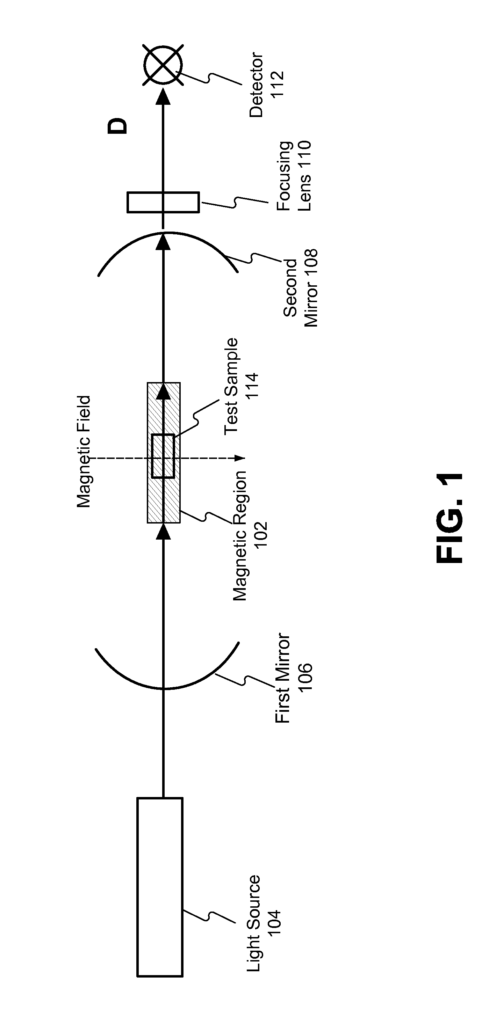
Methods and systems for determining material composition of a test sample may be provided. The test sample may be placed in a magnetic region having a magnetic field. A light beam may be directed at the test sample in the magnetic region. A birefringence in the light beam that has passed through the test sample may be detected. The material composition of the test sample may be determined based on the detected birefringence in the light beam.

What is claimed is:

1. A method of determining material composition of a test sample, the method comprising:

placing the test sample in a magnetic region having a magnetic field;
passing a light beam through the test sample placed in the magnetic region;
detecting birefringence in the light beam that has passed through the test sample;
determining a material composition of the test sample based on the detected birefringence in the light beam.
2. The method of claim 1, wherein placing the test sample in the magnetic region comprises placing the test sample in the magnetic region having an oscillating magnetic field, wherein the oscillating magnetic field is configured to induce contortions in the test sample.

3. The method of claim 1, wherein detecting birefringence in the light beam that has passed through the test sample further comprises:

enhancing the birefringence induced on the light beam by the test sample by using an optical cavity, wherein the optical cavity comprises a first mirror and a second mirror facing the first mirror, and wherein the first mirror and the second mirror are configured to enhance the birefringence by reflecting the light beam in the optical cavity for a predetermined number of times;
collecting the light beam at a predetermined interval at the detector during the light beam being reflected back in the optical cavity; and
determining the birefringence in the light beam at the predetermined regular interval.
4. The method of claim 3, wherein placing the test sample in the magnetic region comprises placing the test sample in the magnetic region located in the optical cavity, and wherein reflecting the light beam in the optical cavity comprises reflecting the light beam through the test sample for the predetermined number of times.

5. The method of claim 1, wherein determining a material composition of the test sample based on the determined birefringence in the light beam comprises:

comparing the detected birefringence with reference values of the birefringence stored in a reference database; and
determining the material composition of the test sample based on the comparison.
6. The method of claim 2, wherein detecting characteristics of the light beam that has passed through the test sample comprises detecting the birefringence in the light beam at multiple values of the oscillating magnetic field.
7. The method of claim 1, wherein passing the light beam comprises passing the light beam perpendicular to a direction of the magnetic field.

8. A system comprising:

an optical cavity comprising a first mirror and a second mirror facing the first mirror;
a magnetic region having a magnetic field configured to induce contortion in a test sample placed in the magnetic region;
a light emitting device configured to emit a light beam to pass through the test sample placed in the magnetic field; and
a detector configured to detect birefringence in the light beam that has passed through the test sample and the mirror cavity.
9. The system of claim 8, wherein the detector is further configured to determine a material composition of the test sample based on the detected birefringence in the light beam.
10. The system of claim 8, wherein the magnetic field is an oscillating magnetic field, and wherein the detector is configured to detect the birefringence in the light beam that has passed through the test sample for different values of the magnetic field.
11. The system of claim 8, wherein the magnetic field is in the optical cavity, and wherein the optical cavity is configured to reflect the light beam passed through the test sample back to the test sample.
12. The system of claim 11, wherein the detector is further configured to detect birefringence in the light beam after the light beam has passed through the test sample a predetermined number times.
13. The system of claim 8, wherein the detector is further configured to detect at least one of: a photon density, a beam diameter, and an energy loss in the light beam that has passed through the test sample.
14. The system of claim 8, wherein the magnetic field is perpendicular to a direction of propagation of the light beam.
15. The system of claim 8, wherein the first mirror and the second mirror are at least one of: a concave mirror, a convex mirror, a plane mirror, and a combination thereof.
16. The system of claim 8, further comprising a delay cavity, wherein the delay cavity is configured to enhance a path length of the light beam that has passed through the test sample by reflecting the light beam a predetermined number of times inside the delay cavity.
17. The system of claim 16, wherein the delay cavity comprises a third mirror and a fourth mirror placed at a predetermined distance from the third mirror, wherein the third mirror and fourth mirror are facing each other.
18. The system of claim 8, wherein the test sample is a biomarker related to a disease.
19. The system of claim 18, wherein the detector is further configured to identify the material composition of the biomarker related to the disease based on the birefringence properties of the biomarker.

20. A system for determining a test sample, the system comprising:

an optical cavity comprising a first mirror and a second mirror facing the first mirror, wherein the first mirror and the second mirror are configured to reflect a light beam in the optical cavity;
an oscillating magnetic field located at a center of the optical cavity, wherein a ramp rate of the oscillating magnetic field is reconfigurable, wherein the optical cavity comprises a first mirror and a second mirror facing the first mirror;
a laser source configured to emit a laser beam at a test sample placed in the oscillating magnetic field, wherein the oscillating magnetic field is configured to induce contortion in the test sample;
a detector configured to collect the laser beam after it has passed through the test sample a predetermined number of times at a predetermined magnetic field value, wherein the detector is configured to determine birefringence induced on the laser beam caused by the induced contortion of the test sample, wherein the detector is further configured to determine a material composition of the test sample based on the determined birefringence.

Share

Title

Method and Systems to Detect Matter Through Use of a Magnetic Field Gradient

Inventor(s)

Carol Y. Scarlett

Assignee(s)

Florida Agricultural and Mechanical University FAMU

Patent #

20140362378

Patent Date

December 11, 2014

Inquire about this intellectual property

Learn more about "Precision Detection with Magnetic Field Technology"