Efficient Reservoir System for Spray Guns

Introduction

This innovative reservoir system for hand-held spray guns provides a powerful solution for industries where precision and efficiency are critical. Whether used in automotive painting, industrial coatings, or home improvement projects, this system enhances the overall performance of spray guns by improving fluid delivery, reducing waste, and ensuring greater control. For companies looking to offer high-performance spray tools, this technology represents an opportunity to meet the growing demand for precision, quality, and operational efficiency in spray applications.

The Challenge: Fluid Control and Waste Reduction in Spray Systems

One of the major challenges in spray applications is managing fluid flow to ensure precision and minimize waste. Traditional reservoir systems often struggle to maintain consistent fluid delivery, leading to overspray, uneven coating, or wasted material. This inefficiency can increase costs, require more frequent refills, and reduce the quality of the finished product. Additionally, many spray gun systems can be cumbersome, making it difficult for operators to manage multiple tasks effectively. There is a growing need for a solution that addresses these issues while providing a seamless, easy-to-use design.

Advanced Reservoir System for Optimal Performance

This reservoir system solves these challenges by delivering a streamlined solution that optimizes fluid control and enhances the precision of spray applications. The system is designed to maintain consistent pressure and fluid flow, ensuring even coverage and reducing material waste. Its innovative structure allows for easy refill and handling, making it user-friendly and efficient. Whether used for large-scale industrial applications or detailed painting projects, this system offers flexibility and performance that elevate the quality and speed of spray operations.

Key Benefits for Multiple Sectors

In manufacturing and automotive industries, this reservoir system improves the efficiency of spray painting and coating processes, reducing material waste and enhancing product quality. Industrial coatings companies can benefit from the system’s ability to deliver consistent results, improving both performance and cost-efficiency. Home improvement and DIY markets will appreciate the system’s ease of use, offering a tool that simplifies projects while delivering professional-level results. Additionally, the reservoir system’s adaptability makes it a valuable tool for both professional contractors and consumers, broadening its market appeal.

Investing in Enhanced Spray Technology

Licensing this efficient reservoir system technology positions your company to meet the increasing demand for high-performance spray applications across various industries. By offering a tool that reduces waste, enhances precision, and improves ease of use, your business can provide a solution that delivers tangible value to professionals and consumers alike. This technology represents a forward-thinking approach to spray gun design, providing a more efficient and effective tool for those seeking precision in their work. It’s an investment in quality, performance, and customer satisfaction, offering a competitive edge in the spray tool market.
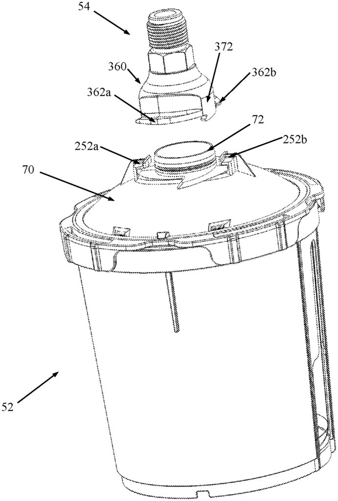
A reservoir system for use with a spray gun. The system includes a cup receptacle and a lid. The lid includes a lid body and a collar. The lid body provides a spout and a platform surrounding the spout. At least a portion of the platform forms a partial helical shape revolving about a central axis of the spout. The collar is rotatably connected to the lid body. Further, the collar includes a lid connector structure configured to connect the lid to the cup receptacle. In some embodiments, the reservoir system further includes one or more of an adaptor, a plug and a shaker core.

What is claimed is:

1. A lid for a spray gun reservoir system comprising:

a lid body comprising:

a spout;
a platform at least partially surrounding the spout, wherein the platform defines a major plane and a partial helical shape declining with respect to the major plane and revolving about a central axis of the spout; and
a wall comprising an outer face adjoining the platform and comprising a portion that is declining with respect to the major plane of the platform;
wherein the partial helical shape begins in the major plane and interrupts the declining portion of the outer face of the wall, and
wherein the lid is configured to directly or indirectly attach to a spray gun.
2. The lid of claim 1, wherein the declining portion of the outer face of the wall comprises a dome shape.
3. The lid of claim 1, wherein the declining portion of the outer face of the wall comprises a conical shape.
4. The lid of claim 1, wherein a first end of the partial helical shape is proximate a transition zone to the major plane and a second end of the partial helical shape interrupts the declining portion of the outer face of the wall.
5. The lid of claim 4, wherein the second end of the partial helical shape terminates at a retention feature.
6. The lid of claim 1, further comprising a collar rotatably connected to the lid body.
7. The lid of claim 6, wherein the collar includes a lid connector structure configured to connect the lid to a compatible cup receptacle.

8. A lid for a spray gun reservoir system comprising:

a lid body comprising a spout and a platform at least partially surrounding the spout, wherein at least a portion of the platform forms a partial helical shape revolving about a central axis of the spout, and
a collar rotatably connected to the lid body;
wherein the collar includes a lid connector structure configured to connect the lid to a compatible cup receptacle.
9. The lid of claim 8, wherein the platform defines a major plane and the partial helical shape declines with respect to the major plane, and further wherein the lid body includes a wall comprising an outer face adjoining the platform and comprising a portion that is declining with respect to the major plane of the platform, and even further wherein the partial helical shape interrupts the declining portion of the outer face of the wall.
10. The lid of claim 9, wherein the declining portion of the outer face of the wall comprises a dome shape.
11. The lid of claim 9, wherein the declining portion of the outer face of the wall comprises a conical shape.
12. The lid of claim 9, wherein a first end of the partial helical shape is proximate a transition zone to the major plane and a second end of the partial helical shape interrupts the declining portion of the outer face of the wall.
13. The lid of claim 12, wherein the second end of the partial helical shape terminates at a retention feature.

14. A reservoir system for use with a spray gun, the system comprising:

a cup receptacle; and

a lid including:

a lid body providing a spout and a platform surrounding the spout, wherein at least a portion of the platform forms a partial helical shape revolving about a central axis of the spout, and
a collar rotatably connected to the lid body;
wherein the collar includes a lid connector structure configured to connect the lid to the cup receptacle.
15. The reservoir system of claim 14, wherein the cup receptacle includes a cylindrical side wall extending from a base end to an open end and defining an inner cavity, and further wherein an aperture is defined in the side wall that is open to the inner cavity for viewing contents of the inner cavity from an exterior of the cup receptacle, and even further wherein the aperture has a non-uniform circumferential width.
16. The reservoir system of claim 15, wherein the aperture extends from a first side proximate the base end to an opposing, second side proximate the open end, and further wherein a circumferential width of the aperture at the first side is greater than a circumferential width of the aperture at the second side.
17. The reservoir system of claim 14, wherein lid body includes an outer face defining a continuous dome shape, and further wherein the platform defines a ramp surface having a first ramp segment extending from a first end to a second end, the first end being longitudinally above the second end relative to an upright orientation of the lid, and even further wherein the ramp surface segment projects into the dome shape of the outer face.
18. The reservoir system of claim 17, wherein the ramp surface further includes a second ramp segment extending from a first end to a second end, the first end of the second ramp segment being adjacent and longitudinally above the second end of the first ramp segment, and further wherein the lid body forms an undercut at an intersection of the first and second ramp segments, the undercut projecting into the dome shape of the outer face.
19. The reservoir system of claim 17, wherein a radial width of the first ramp segment at the first end is less than a radial width of the first ramp segment at the second end.
20. The reservoir system of claim 14, wherein the collar includes a ring and a plurality of tabs projecting from an underside of the ring, a portion of the lid connector structure being carried by at least one of the tabs, and further wherein the ring has a variable radial width.
21. The reservoir system of claim 20, wherein circumferentially adjacent ones of the tabs are separated by a circumferential opening, and further wherein a radial width of the ring decreases at a location longitudinally aligned with at least one of the circumferential openings.
22. The reservoir system of claim 20, wherein the ring defines at least one slot that is aligned with a corresponding one of the tabs.
23. The reservoir system of claim 14, further comprising an adaptor configured to selectively connect the spout with a spray gun inlet.
24. The reservoir system of claim 23, wherein the lid and the adaptor include complementary connector features for selectively mounting the adaptor to the lid.
25. The reservoir system of claim 23, wherein the adaptor includes a tubular member and a base projecting from the tubular member, and further wherein the tubular member terminates at an end and the base defines a tracking face opposite the end, and even further wherein at least a portion of the tracking face forms a partial helical shape corresponding with the partial helical shape of the platform.
26. The reservoir system of claim 23, wherein the adaptor further includes at least one lock structure projecting from an outer face of the base.
27. The reservoir system of claim 26, wherein the at least one lock structure extends from a first end to an opposing second end, and defines an abutment face, an upper face opposite the abutment face, and a guide face opposite the base, and further wherein a geometry of the abutment face in extension from the first end to the second end differs from a geometry of the upper face in extension from the first end to the second end.
28. The reservoir system of claim 27, wherein the upper face defines an insertion section extending from the first end and a locking section extending from the insertion section in a direction of the second end, and further wherein a major plane defined by the insertion section segment is non-coplanar with a major planed defined by the locking section.
29. The reservoir system of claim 28, wherein the upper face further defines a tail section extending from the locking section in a direction of the second end, and further wherein a major plane defined by the tail section is non-coplanar with the major plane defined by the locking section.
30. The reservoir system of claim 29, wherein a shape of the tail section is a partial helix.
31. The reservoir system of claim 27, wherein the guide face defines a first region extending from the first end and a second region extending from the first region in a direction of the second end, and further wherein the first region defines a uniform radius relative to a centerline of the tubular member, and even further wherein the second region defines a tapering radius relative to the centerline in extension from the first region toward the second end.
32. The reservoir system of claim 26, wherein the lid further includes at least one retention structure configured to engage the at least one locking structure upon rotation of the adaptor relative to the lid.
33. The reservoir system of claim 14, further comprising a plug for selectively sealing the spout, the plug including a plug body and a lip, wherein the plug body defines a closed end opposite a leading end, and further wherein the lip projects radially from the leading end, and even further wherein the lip defines a plurality of grasping tabs.
34. The reservoir system of claim 33, wherein the plurality of grasping tabs are equidistantly spaced from one another.
35. The reservoir system of claim 33, wherein the plurality of grasping tabs includes exactly three grasping tabs.
36. The reservoir system of claim 33, wherein the plug body defines a stepped outer diameter in extension from the closed end to the leading end.
37. The reservoir system of claim 14, further comprising a shaker core configured for selective mounting to the lid, the shaker core having a longitudinal length such that upon mounting to the collar, the shaker core extends beyond the spout.
38. The reservoir system of claim 37, wherein shaker core defines opposing, first and second ends, and further wherein an inner diameter of the shaker core at the first end is greater than an inner diameter of the shaker core at the second end.
39. The reservoir system of claim 38, wherein the shaker core further include an annular shoulder projecting radially inwardly from the hub adjacent the first end, the annular shoulder defining a ledge for abutting a corresponding surface of the collar.
40. The reservoir system of claim 39, wherein the shaker core further includes at least one key body projecting from the ledge in a direction of the first end, wherein the key body is configured to be received within a corresponding notch defined by the collar.

Share

Title

Reservoir systems for hand-held spray guns and methods of use

Inventor(s)

Anna M. Hegdahl, Alexander T. Ebertowski, Scott D. Gullicks, Andrew R. Henry, Stephen C. P. Joseph, Sabeel Ullah

Assignee(s)

3M Innovative Properties Co

Patent #

10689165

Patent Date

June 23, 2020

Inquire about this intellectual property

Learn more about "Efficient Reservoir System for Spray Guns"