Experience the Future of Structural Monitoring with Triboluminescent Optical Fiber Sensing
Introduction
Imagine a sensor so intuitive that it lights up at the slightest hint of structural stress or damage, giving you instant, visible feedback. Our patented “Triboluminescent Optical Fiber Sensing Patch” (Patent #10386305) does just that, combining cutting-edge technology with practical application to bring you a revolutionary tool in structural health monitoring.
Why It Matters
In industries like aerospace, civil engineering, and energy, ensuring the integrity of structures is non-negotiable. Traditional sensors often require complex data analysis and may miss subtle signs of stress that could lead to serious issues down the line. That’s where our triboluminescent sensor comes in—it offers a straightforward, real-time solution that’s both reliable and easy to understand.
The Innovation
This sensing patch integrates triboluminescent materials with optical fibers, creating a sensor that visibly responds to mechanical stress or strain by emitting light. It’s like having a built-in warning system that alerts you the moment something isn’t right, without the need for intricate equipment or time-consuming analysis.
Key Benefits
- Instant Feedback: Visual indication of stress or damage means you can address issues immediately, reducing downtime and preventing costly failures.
- Versatility: Whether it’s embedded in an aircraft wing, a bridge, or a pipeline, this technology adapts to a wide range of applications, offering robust monitoring across different environments.
- Safety and Efficiency: Early detection leads to proactive maintenance, ensuring safety and maximizing the lifespan of critical assets.
The Opportunity
Don’t settle for reactive solutions. Be proactive, be innovative, and license our triboluminescent optical fiber sensing patch today. With this technology in your arsenal, you’ll be at the forefront of the next generation of structural health monitoring.
- Abstract
- Claims
We claim:
1. A sensing patch comprising:
8. A system comprising:
a sensing patch optically coupled to the photodetector, wherein the sensing patch comprises:
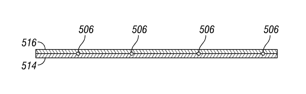
an optical fiber comprising an outer surface, wherein at least a portion of the optical fiber is at least partially embedded within the substrate;
15. A method of forming a sensing patch comprising:
Share
Title
Triboluminescent optical fiber sensing patch
Inventor(s)
Okenwa Okoli, David Olawale
Assignee(s)
Florida State University Research Foundation Inc
Patent #
10386303
Patent Date
August 20, 2019